K2 SSB Module - Night One


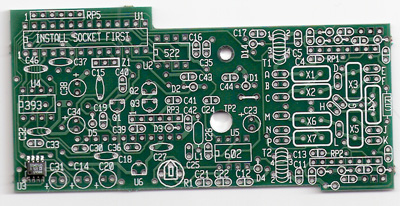
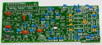
I started working on the SSB module tonight. A year or two ago I would have thought
that this was a big project. Now it is not a big deal at all. I spent about 60-90
minutes tonight sorting the parts and installing the capacitors.


From the flatbed scanner:


From the digital camera:


It is amazing how fast you can work once you get into a rhythm. I wish that I had
started this kit Monday night. Maybe with some luck I can get it working by this weekend.


The internal ATU is the next kit after this. It is sitting on the bench next to this
kit.  :-)


K2 - Day Twenty Four... sort of


I have lost track of how many days I have spent 30-60 minutes here or there trying
to track down a low power/Hi Current issue.


It turns out that I had two issues:


1. Low power... about 4-6w instead of 14-15w. After looking at and touch every component
in the PA Bias and PA circuits it looks like there was something wrong with T4. I
am not sure what... but the problem has been resolved.


2. High Current... looks like L16 and/or L17 in the Low Pass Filter was the problem.
I removed them and rewound them.


I spent about 6 hours working on the radio today. (About 4 hours of testing... about
2 hours of construction/repairs.)


I am happy to have a working radio. I hope to be able to spend a little time tomorrow
tweaking up the 10m/12m power levels and then button up the radio.


I am ready to move on to the ATU and SSB module kits next.  :-)


K2 - Day TwentyThree


I am trying to track down why my power output is low. I have a couple of hours into
this today... my vacation day (use it or lose it)


----Snip from the email that I sent to the
Elecraft Reflector----


K2 gurus:


I got a note from Gary (support) and Don (w3fpr) with some ideas.


--I checked the low pass filters and the number of turns.

--I validated that T4 is oriented the right direction --No burnt relays

--8R/8T are ~8vdc (R-7.87/T-7.815)

--8R on transmit goes to 0.245vdc

--I clipped W1 to test for PA feedback (no change)


--I removed the bottom panels and cleaned up a couple of joints as a CYA


--Removed and rewound LP for 80m


--Checked & resolder the connections of toroids for 20/30, 15/17, & 40


--Repeaked (on receive) all of the band pass filters with a signal generator


--Repeaked (on transmit) all of the band pass filters


I made some progress: (Original Test... and after some rework)

--Freq-----1 Test----1 Msg----2 Test----2 Msg

 3.750mhz  2.5w     
Hi Cur   2.3w      Hi Cur

 7.100mhz  6.1w     
Hi Cur   6.6w      Hi Cur

10.100mhz  0.3w     
Hi Cur   4.9w      Hi Cur

14.100mhz  0.3w     
Hi Cur   5.7w

18.100mhz  9.5w              
7.3w


21.100mhz  4.1w        
      5.0w

24.900mhz  0.5w             
 4.9w

28.200mhz  6.0w             
 6.3w


As you can see I am now getting ~5w on all bands except for 80m. I suspect
that the toroid cleanup might have been part of the answer for 20/30 and tweaking
the band pass brought 10/12 into better alignment.


On the three bands that I get a high current message it appears at the
peak power out and does go away if the power is reduced. Any chance that I am only
seeing power out of Q7 or Q8 instead of both of them?


>

K2 - Day Twenty One & Twenty Two


Thursday was day 21. I spent the afternoon trying to trouble shoot
an RF issue. I built the RF probe and poked around the radio while I was on the phone
with Scott @ Elecraft HQ. It is hard to poke around some of the RF amp sections because
the bottom cover/heat-sink is in the way.


-------------


Saturday was day 22. I went over to N0FP's QTH. He has an O-Scope.
Between two of us we went thru the schematic and compared notes with the O-scope readings.
We were seeing RF thru the entire chain where we were expecting it.... just not enough
RF.


Using the scope we able to measure the DC and the RF. His scope was fast enough that
we were able to see a lot of detail in the RF. Even though T3 tested out properly
it looked like the likely problem. I rewound it and put it back into the circuit.
I also borrowed some small heat-sinks that would fit on the PA transistors so that
we could test the radio without the rear cover.


I am now seeing the proper amount of RF coming out of the rig. I need to take one
more pass thru tuning up the Band Pass Filters. Once that is done I need to test the
output of each band to make sure that all looks good.


At this point it looks like the circuits are playing as expected. Next phase is to
hook up the speaker and close up the case then the basic build is complete.


I have the SSB and ATU option kits to put together next.


K2 - Day Twenty


Our weather has become cool and rainy, snowy, and ice covered rather early this fall.
It appears that I am already visiting in the inside work bench a little more and a
little earlier than usual. (Not that inside projects are bad.)


I took today as a PTO day at work (burning up time before the end of the year.) I
decided to spend the majority of the day working my Elecraft K2 project. Looking
at my blog it appears that last time that I worked on the kit was June 20 which is
about 5 months ago... wow that is a long time.


I spent about 6 hours today working on the project. Today's focus was installing the
last batch of capacitors, resistors, and then winding cores and transformers. Tonight
at 8:30 I got the PA transistors installed and the case put back on the radio. The
next big step is the Phase 3 alignment.


This next chunk of testing and alignment will validate that I installed all of the
proper pieces in the proper spots. So far I have had minor issues with each phase
largely due to dumb things on my part. Each of them was resolved with some troubleshooting,
emails, and the occasional phone call to the support folks.


I am not sure if I will get back to the project this week as the calendar is looking
pretty full. Worst case... I have another day of PTO planned for next week.    I
would like to get the basic QRP CW rig finished and checked out. I still have the
Tuner and SSB option kits to install to finish out the basic rig.


My goal is to be able to finish the radio with the above options and then be able
to order, build, and validate the transverter option kit prior to the January VHF
contest. (Ok... my first goal was to have the radio ready for the 2008 Field Day weekend...
I kind of missed that goal... life got in the way again.)




By: Comments Off

K2 - Afternoon Nineteen


I had an issue with the 40m and IF alignment. After talking with Elecraft support
to get an idea of where to look I discovered that R12 on the control board was missing.
It turns out this is tied to the same issue I had with R11. Someone had sent me an
email early in my project stating that R11 and R12 were no longer required. Both are
critical pieces of the control board. Once I installed R12 things were back on track.


I heard my first CW and SSW signals on my K2.


I am now in the Part 3 Assembly Steps. I just completed the first batch of resistors.
It is time to clean up for dinner. Maybe with some luck and I can try to squeeze in
some more bench time through-out the weekend.


Right now it is not looking too likely that I will have the K2 completed for Field
Day. As a backup plan I ordered a 350hz filter for my Icom 706MKIIG. The 706 will
be my Field Day 2008 rig if the K2 is not complete.


By: Comments Off

K2 - Night Eighteen


After about 2 days of going in circles trying to track down my alignment problem.
I talked with Scott and emailed Gary at Elecraft a couple of times. After a bunch
of troubleshooting I decided that T5 seemed like the only thing left.


After a visual inspection it looked ok but I decided to remove it and rewind
it anyway. That seemed to be the magic needed to make the VFO circuit work properly.


The rest of the alignment pieces checked out so I am headed onto the next build phase.
There is a VHF contest this weekend plus some family stuff going on so I don't think
that I will get back to the K2 project until Sunday night or Monday night.


By: Comments Off

K2 - Evening Seventeen

This should have been posted yesterday but my site was moving to another server so I did not want to post while things were in-flight.


I am having some problems with the Testing and Alignment Phase.  It seems like
the VFO feedback is telling the VFO that it needs to go lower. My R16 and R30 voltages
are not reading properly. I have been working with Scott and Gary at Elecraft trying
to trouble shoot this. So far we are still testing.
By: Comments Off

K2 - Day Sixteen


While the family was in the metro I spent the afternoon working on the K2. A lot of
the inductors are now in place, some of the filters, and some of RF chokes.


I am ready to begin the next section of alignment and testing. When I apply power
I initially hear the the relays move but then nothing else. The main display does
not power up.


I am not sure what the problem is. I don't see any shorts. I don't see any missed
soldier connections. As I initial trace the 14vdc it appears that there is power on
the RF board. All of resistance tests check out.


Hmmmm.... I need to scratch my head and think about this a bit.