By:
Category:
Comments Off

Wow.... running on 6m tonight

A very cool evening. I decided to turn on the rig for a few minutes before dinner and worked 35 Q's on a 6m opening.


After the first contact with WA3LKT I had Rege hang on so that he could be the first
6m contact in the log for Ben KD0JZK. A 6m band opening was a bit over whelming for
Ben so I need to work on the pile-up skills.  When there is an opening we are
moderately popular from EN25.


That was more fun than running on HF during a contest.


73 de NG0R


By:
Category:
Comments Off

30m Oscillator

I have been interested in building a transmitter for QRSS activities. On 30m the activity is located at 10.140000 MHz to 10.140100 MHz (100 Hz wide sub-band). I happen to have quite a few crystals on hand for 10.140 so I thought it was time to  start building a circuit that could emit some RF.


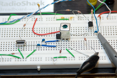
My initial bread board design is shown below. I built an oscillator and once that
was functional I added simple NPN follower to the circuit. The original oscillator
design is derived from a W7ZOI design for 40m. (I like the oscillator design because
it provides a quite a bit of feedback so it has a reliable start but is stable after
being in key down for 45 minutes.)


It comes up on frequency at 10.138 and is pretty stable. It looks like I will need
to work up an inductor & capacitor pair that I can use to move it up the band
a little bit.


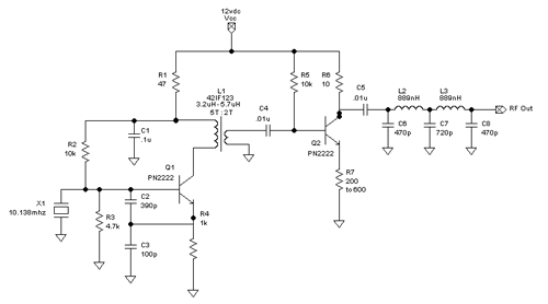
After a few hours of building and testing I translated my changes via pencil on to
the paper schematic and then went back to the computer to update the design in TinyCad.
I also called N0FP to get some help using the AADE filter software so that I could
add a low pass filter to the output of the follower. N0FP also helped me tweak the
bias for the Q2 follower transistor.


Here is a picture of the some test gear. It is nothing special but it is enough to
see what you are building. I was able to adjust L1 to tune out quite a bit of the
harmonic properties. The spectrum analyzer is an inexpensive model that is good to
about 550mhz. The analyzer combined with the 60mhz oscope really helps to visualize
the RF in the project.


The TinyCad schematic above shows the changes to R6 & R7 and then the Chebyshev
low pass filter. Those are the next changes that I will add to breadboard and then
retest the circuit.


Future ideas/goals:


--Move it to a copper board with Manhattan construction for additional stability and
testing.


--Add some additional LC to swing it into QRSS sub band.

--Add a PIC 16F628A to generate the QRSS CQ message.

--Use the PIC to generate some visual feedback during operation.


--Investigate rescaling it to another band

--Etch a board for the final project


I had a blast on Saturday building the initial prototype. It was very rewarding to
put the pieces on the breadboard and to see RF start showing up on the scopes. There
is a ton of learning experience that is gained during these projects.


73 de NG0R


By:
Category:
Comments Off

Rockmite mods

Here are some interesting mods to the Rockmite.


http://www.qsl.net/5z4ft/rock.html


I need to spend some time bonding with mine. I have had it for probably 6-7 years...
maybe I should bring it camping this summer. It might be fun to use at night as things
start to wind down for the night.


I have been thinking about buying a couple of the kits for Jacob and Ben. Then they
could have their own rigs. :-)

By:
Category:
Comments Off

KD0JZK on the air

Here is a picture of Ben on the air this morning trying to make a contact on the magic band.


Here Ben's first contacts in the log from last night and this morning.


Date

(GTM)

Time On

(GMT)

Time Off

(GMT)

Band

His Call

My Call

His RPT

My RPT

Notes

01/30/10

00:38

00:42

2m

KC0ZSX

KD0JZK


Hutchinson Repeater

Bob


01/30/10

00:40

00:42

2m

KC0PVC

KD0JZK


Hutchinson Repeater

AJ & Sam


01/30/10

02:11

02:25

2m

N0FP

KD0JZK


146.40 mhz – local chat

Ford


01/30/10

02:35

02:38

10m

N0FP

KD0JZK

2x5

5x5

28.310mhz – the band was virtually closed even 8 miles away.

01/30/10

16:59

17:01

2m

WB0TRA

KD0JZK


146.40 mhz – local chat

Lee


I probably need to order a paper log book for Jacob and Ben (one book for each of
them) so that they can keep track of stuff. Right now I built a simple paper log using
OpenOffice and sent it to the laser printer so that we could get going.


By:
Category:
Comments Off

Two more hams in the family

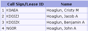
Jacob (11) and Ben (9) passed their technician class test on Saturday 1/23/2010. Their call signs showed up the ULS database tonight. 


They have been asking me everyday if they have been posted to the ULS.... now that
they that have their calls and are truely licensed they want me to start working on
the vanity callsigns. --pretty funny.


4 of the 5 members of our immediate family are now hams. Joe (7) has a year or two
before he will be ready to start studying. Since his brothers got their ticket he
is now talking about getting it.


By:
Category:
Comments Off

PIC LCD notes

Here is an interesting site that talks about the pins for the Hitachi 44780 LCD controller.


http://lcd-pic.blogspot.com/


Pin Description


1 Vss, Ground

2 Vcc, +5V supply

3 Vee, Contrast Voltage

4 R/S, Instruction / Data Mode select

5 R/W, Read / write

6 E, Enable

7-14 D0-D7 Data lines

15 +Led

16 -Led


I am still digging for some information so that I get write a basic "hello world"
program in BASIC. Hopefully I will find a couple of hours of quality time in the near
future to bond with the compiler and the PIC-EL III board.


By:
Category:
Comments Off

WSPR results?

What does my shack do when I am stuck working and can't play?  --Sit and listen to WSPR beacons
and post them to the internet.


The table below shows all the unique stations that I have heard over the past 3-4
days that are doing better than 1000 miles per Watt sending WSPR.  Most of these
have been heard using my Elecraft K2, 160m antenna, WSPR running on Linux. (The
160m antenna is a 56 foot tall shunt loaded tower with about a dozen radials.)


Date and Time

Sending Call

Freq

Pwr in Watts

Miles

Miles per Watt

01/17/10 04:56 PM

W3PRB

10.1402410

0.001

1572

1572000.00

01/15/10 07:40 PM

W1BW

10.1401490

0.100

1856

18560.00

01/17/10 04:50 PM

DL1EL

10.1401380

0.500

7047

14094.00

01/19/10 02:12 AM

EA1RJ

3.5941420

0.500

6850

13700.00

01/17/10 09:36 PM

WJ2V

10.1401430

0.200

1747

8735.00

01/16/10 01:00 PM

N0GSZ

7.0401070

0.200

1682

8410.00

01/15/10 08:36 PM

IQ4DJ

10.1402330

1.000

7618

7618.00

01/18/10 03:48 PM

PA2PF

10.1402230

1.000

6695

6695.00

01/17/10 02:50 AM

G7DOM

3.5940950

1.000

6240

6240.00

01/15/10 07:38 PM

K4MF

10.1402070

0.500

2207

4414.00

01/17/10 05:36 PM

DG1SGH

10.1402140

2.000

7212

3606.00

01/19/10 02:18 AM

N1DYL

3.5940930

0.500

1799

3598.00

01/16/10 10:54 PM

EA8/LA3JJ

7.0401710

2.000

7071

3535.50

01/15/10 09:38 PM

EA1YO

10.1402590

2.000

6783

3391.50

01/16/10 07:48 PM

WA4DAW

7.0401050

0.500

1548

3096.00

01/19/10 05:08 PM

GI6ISW

14.0971540

2.000

5964

2982.00

01/15/10 07:50 PM

K7LG

10.1401730

1.000

2389

2389.00

01/16/10 05:08 PM

K0AWU

7.0400270

0.100

224

2240.00

01/17/10 01:02 AM

W7RDP

7.0400680

1.000

2133

2133.00

01/15/10 07:38 PM

W3HH

10.1401620

1.000

2083

2083.00

01/18/10 08:18 PM

NJ6D

10.1401930

1.000

2018

2018.00

01/17/10 02:50 AM

N7KJW

3.5941150

1.000

1963

1963.00

01/17/10 05:22 PM

JQ2WDO

10.1402200

5.000

9604

1920.80

01/17/10 02:08 PM

K0FT

3.5940770

0.500

887

1774.00

01/17/10 09:44 PM

W3FIS

10.1401140

1.000

1749

1749.00

01/17/10 02:08 PM

VK6POP

3.5941010

10.000

17008

1700.80

01/16/10 03:54 AM

WA3ETD

7.0401070

1.000

1670

1670.00

01/16/10 05:20 PM

VA2DC

7.0400980

1.000

1625

1625.00

01/15/10 08:24 PM

WB3ANQ

10.1401990

1.000

1608

1608.00

01/18/10 05:16 PM

K8KCX

10.1402460

0.500

800

1600.00

01/15/10 10:18 PM

AI4RY

10.1402380

1.000

1592

1592.00

01/15/10 07:38 PM

W3CSW

10.1402780

1.000

1562

1562.00

01/19/10 05:00 PM

OE3BWW

14.0971870

5.000

7622

1524.40

01/16/10 09:22 PM

DF6MK

7.0400380

5.000

7427

1485.40

01/18/10 03:28 PM

DC6MY

10.1402330

5.000

7310

1462.00

01/17/10 05:36 PM

HB9BYC

10.1401580

5.000

7277

1455.40

01/19/10 05:06 PM

DL7VEA

14.0971420

5.000

7168

1433.60

01/17/10 04:28 PM

DL1BNO

10.1401950

5.000

7111

1422.20

01/17/10 05:14 PM

DF5FF

10.1402480

5.000

7093

1418.60

01/18/10 04:12 PM

DL5ZAA

10.1401620

5.000

7085

1417.00

01/17/10 03:12 AM

DH8SA

3.5941150

5.000

6998

1399.60

01/16/10 11:42 PM

EA4AS

7.0400880

5.000

6967

1393.40

01/17/10 05:24 PM

DF2JP

10.1401630

5.000

6900

1380.00

01/15/10 07:44 PM

N5BFB

10.1401860

1.000

1369

1369.00

01/17/10 02:56 AM

PA1NL

3.5940990

5.000

6782

1356.40

01/18/10 03:20 PM

ON7KO

10.1402110

5.000

6763

1352.60

01/19/10 02:16 AM

OH8GKP

3.5940880

5.000

6719

1343.80

01/15/10 07:38 PM

W3PM

10.1402330

1.000

1326

1326.00

01/16/10 11:34 PM

G8HXE

7.0401630

5.000

6253

1250.60

01/18/10 09:30 PM

WA7RED

10.1402570

1.000

1143

1143.00

01/15/10 10:58 PM

WA5ETV

10.1401960

1.000

1103

1103.00

01/19/10 02:10 AM

W0AEW

3.5940760

1.000

1044

1044.00


Okay, that was my lunch time distraction... time to go back to work.


73 de NG0R


By:
Category:
Comments Off

Directional Coupler (Version Two)

This project is the follow-up to the Pine
Board Directional Coupler
that I built & tested a couple of weeks ago. That
project was largely based upon information from Sprat and Elecraft. (Links to the
info is at the end of the post below.)


I plan to use this with my Spectrum Analyzer as I need a safe way to sample levels
low enough for the scope. (I am not a fan of using attenuation pads if "real power"
might be involved as they could open up and present high power to the test tools if
they fail. Most pads are only rated at 2w.)


Goals:


  • Build a directional coupler with a port that is -20db from the reference signal. I
    am primarily working at HF frequencies for my current design work but would like to
    have basic VHF or even moderate UHF coverage if possible.


  • The ability to run real power through the unit if needed. (100w)


  • It should be easy to build.


  • It should allow for reproducible test results across other replicas of the unit.


The wire lead lengths were minimized where possible. Most of the part could easily
be scrounged from a junk box if you are a well equipped hobbiest... or my case some
of the parts from the internet. (Digikey, eBay, and kitsandparts.com)


Schematic and parts:


2 - T50-43 toroid (kitsandparts.com)

3 - BNC connectors (eBay from China)

2 - 100 ohm 1w resistors (non inductive from Digikey)

1 - standoff (Digikey)

1 - Hammond 1590B case (Digikey)

Misc Wire (12 gauge and 20 gauge from the junk box)


If you follow the schematic as guide a to the physical wiring of this project you
should be fine. (Think of it as plumbing.)


I am going to leave the theory explanation to others because I do not completely
understand the exact science that is going  in that little box well enough to
be able to explain it to others. Check the links at the end of this post and I will
give you some good sites to visit for more information.


Measurement:


I went to N0FP's QTH to do the measurements.
We did a baseline calibration to normalize things like the cables, signal generator,
and the RF power meter. We used a Boonton
4220 RF power meter
for this round of data capture. I plotted everything manually
into OpenOffice on my laptop and then brought the data home where I could work with
it in more detail. (I have the data from 1mhz to 1100mhz)


The new coupler is at ~ -20db  from 1mhz to 120MHz.


--It is flat within .5db from 1mhz to 125mhz.


--It is within 2db +/- out to near 400mhz.


What does the data mean:


Looking at the graph shows that it is a good HF and VHF coupler but then loosens up
at UHF. I wanted to try to understand why it is moving around at UHF. The final project
has shorter wire lengths than the original Pine Board version but the trends were
similar. (I plotted {in yellow} a low power coupler from MiniCircuits as part of
the test. It was something that N0FP had on hand while we were testing so it was an
interesting comparison.)


After looking at the data I decided to plot the wire length to see if maybe we seeing
goofy response because of a 1/4 or 1/2 wavelength of wire. The table below plots the
number of turns, DB of coupling, wire length, frequency.


Sure enough it appears that the wire length is correlating to the data that I had
plotted from the couple of test runs. I think that it is possible to make this stable
at higher frequencies by moving from a -20db design to a -30db design. The challenge
is that the power levels at -30db might become low enough for small signal work that
the signal simply disappears in some cases.


Summary:


  • I have a nice directional coupler that is very accurate for HF and VHF testing. (It
    is usable at VHF with the reference table.)


  • I have not (yet) tested it with 100w in but I would have no concerns with it
    at that power level. (Most of my testing will not be higher than 5-10w.... probably
    even lower than that.)


  • It is a pretty simple project that can be assembled in less than two hours.


  • The accuracy is reproducible as long as excess wire lengths are kept under control.


  • The parts are all readily accessible.


Links:


GQRP/SPRAT article by David
Stockton - G4ZNQ


http://michaelgellis.tripod.com/direct.html


Calculator


http://www.elecraft.com/manual/CP1%20Manual%20Rev%20A.pdf


http://mjrainey.googlepages.com/qrppinlinedirectionalwattmeter


http://www.microwaves101.com/encyclopedia/directionalcouplers.cfm


http://www.e-meca.com/tech_papers/directional-coupler-specs.php


By:
Category:
Comments Off

WSPR - 30m

While I was working today and sitting on conference calls I decided to leave my radio and computer on to listen to 30m WSPR and post spots to the internet.


http://wsprnet.org/drupal/wsprnet/map


I heard two stations from Europe which I thought that was pretty neat.


I heard IQ4DJ when the beacon was running 50mW and 1w.  That is a pretty good
path for 50mW.


Today is the first time that I have played with WSPR. It looks pretty neat and is
going to be worth designing a radio for that portion of the hobby. It will probably
be a crystal driven rig since I have not yet moved up to DDS designs... yet. 
:-)


---

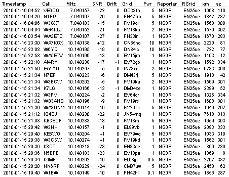
One update @ 11pm local.   Here is the list of unique stations that I heard
today with WSPR.


By:
Category:
Comments Off

DDS from Analog Devices

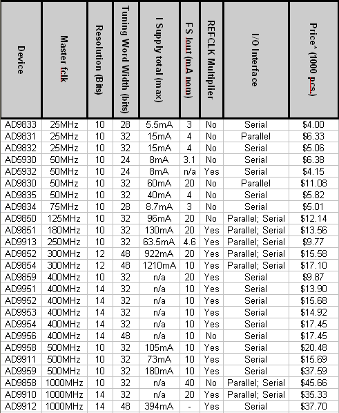
I am doing some initial research on readily available DDS chips. Analog devices has nice web page that allows you to download an Excel doc based upon your query for devices. (Click
on the table below to get to the exact page that has the Excel export options.)


http://www.analog.com


When time permits I need to look around at some other vendors to see what else is
available to the marketplace.