DDS & XO Daughter Boards
I own several DDS and XO (programmable oscillator) cards.
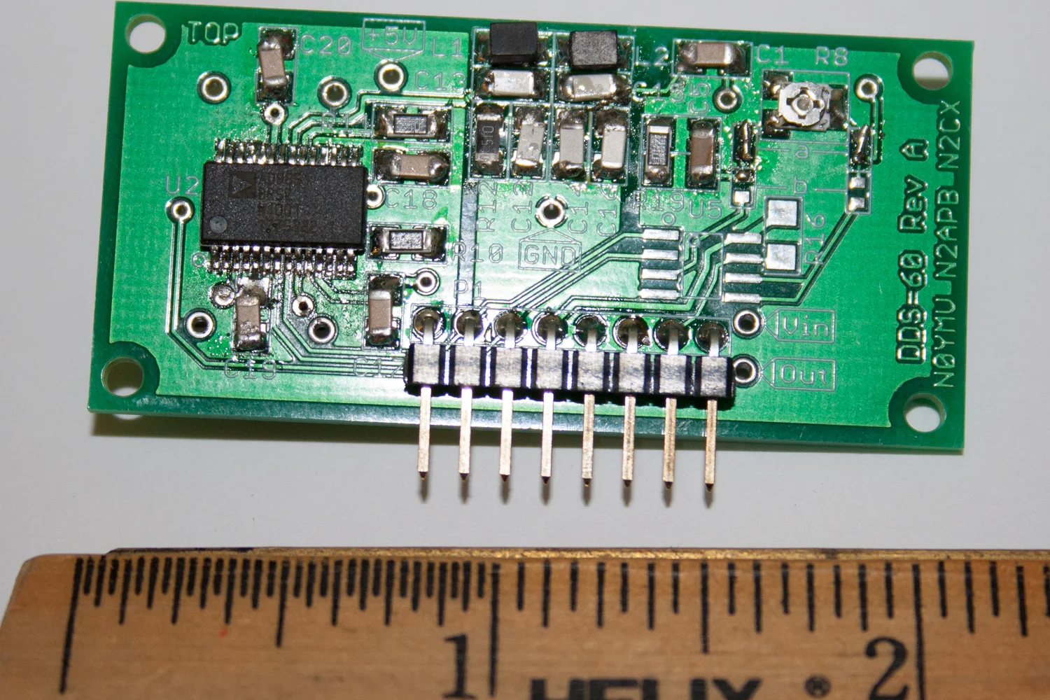
I have a nice DDS60. I have used this with my PIC-EL and an Arduino for previous work bench projects. (I also have some AD9850 andAD9851 adapter cards from eBay.)
DDS60
I also have a nice si570 card from AA0ZZ / KangaUS which is pin compatible with the DDS60/DDS30. I use with the my Pic-EL from AA0ZZ.
AA0ZZ si570 card offered by KangaUS
I am looking to run some more si570 experiments but this time interfaced to the ATMEL AVR platform initially with an Arduino. I was doing searching for some code examples and run into a nice daughter board by WA6UFQ that I liked so much that I ordered one a couple of days ago.
WA6UVQ si570 controller card
si570 controller card example in Eagle
One of the design/interface challenges that I am trying to noodle through is:
- Do I setup the daughter board with the minimum number of pins
(minimum of 5 pins or 6 pins to use a standard sized part) - Do I setup the board similar to the DDS30/DDS60 pin-out
- Do I setup the board similar to the WA6UFQ board that is coming in the mail
I really dislike having similar boards with dissimilar pin outs. At best it drives confusion and at worst it drives destruction when you mis-wire something and let the smoke out.
Initially I am leaning towards option #1 but I am still thinking about it. I have little bit of time since I have not converted the schematic to a board layout nor taken it to the CNC.
I don't have the proper voltage regulator on hand or I probably would have already milled out the board a few hours without as much thought about the what if portion of the design. (It is a prototype after all)
73 de NG0R


