By: Comments Off

Some personal development

I am a little behind/delayed in posting to the blog.​ I have been moderately busy between family and work activities the last couple of weeks.

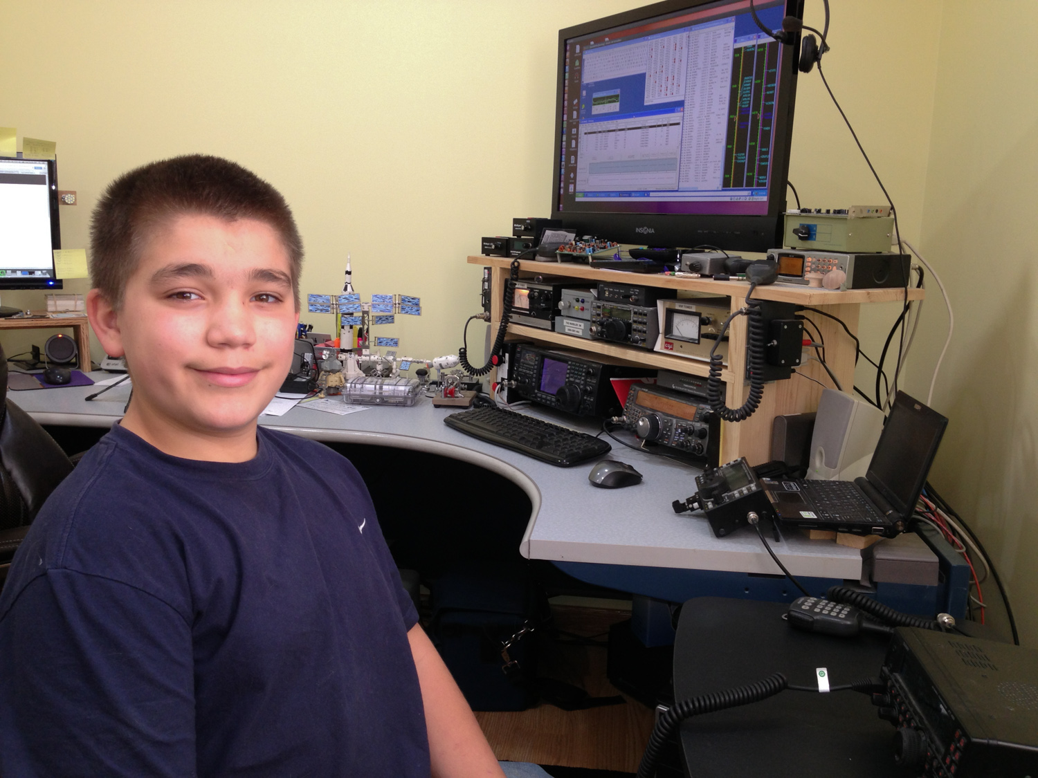
Recently the boys (Jacob 14, Ben 12, Joe 10) expressed some interesting learning to do some programming. As part of their home schooling Cristy found an online site that teaches kids to use javascript to do some graphical oriented projects. Ben was immediately taken by the project other than he wants to write stuff that can run natively on their computers (outside of the sandbox.)

​This started a new path (aka: black hole, time suck) to get all of the boys setup for some development projects.​ We (the parents) decided that the boys should go through some various computer development and electrical projects to help them experience some different areas of learning. (With home schooling there is an opportunity to be creative.)

​I setup each of their personal computers (running Ubuntu 12.04) with SPE (Stani's Python Editor) and DropBox.  We will use Python as the initial language that we will work through as a family. In order to share the files within the family and potentially some external friends we are going to use DropBox to sync the files. Everyone will get a directory of their own but will also be able to see/share the code examples of the larger group. (I use a Mac in my office for my primary workstation so I am using a different editor. I also have  an Ubuntu machine with a 32" screen that we use for the group discussion sessions.)

​I am using a mix of teaching elements; some video from the internet, several different internet sites as a reference, and I purchased a booked call "Python for kids".  The book takes you through the various basic elements and eventually gets them to the point where they can write a game.

Ben is working so far ahead of his brothers that it is hard for me to work at two different levels between the kids. (I have to do my own research, then come up with a lesson, and then come up some assignments... all while trying to keep everyone engaged.)  To help keep Ben's mind in check I am trying to get him to spend his extra energy working with an Arduino using C.  My hope is that this will keep the three boys more closely aligned pace wise in the Python lessons a couple of nights per week.

This spurred me to sign up for some free online college level courses in a couple of different programing languages. I am not exactly sure how I am going to manage this time wise yet but I will need to decide if it is important and if so make it a bluechip for me. (I expect work to get crazy soon too.)

Overall this is good. It has negatively impacted my available time to work on my radio design project, time for Arduino development, and Raspberry PI exploration. I am hoping that my extra time working with the kids will also help me improve my rusty development skills so that it comes back around full circle to my other projects.

It will be interesting to see how far the kids go with the development projects. If they can get through Python we will consider C or Java for something that we can target for multi-platform and/or mobile development. (We have plenty of iOS and Android devices.)​

73 de NG0R

By:
Comments Off

Parts in the mail

Somedays the mail can be a beautiful thing....

iPhone photo - four Arduino Nanos

iPhone photo - four Arduino Nanos

iPhone photo - 20x4 I2C LCD

On 1/27/13 I ordered some more parts for Arduino (and PIC) prototype work. Today 2/4/13 some of those parts arrived via eBay from China. (Faster than some parts that I ordered in the US on the same day that have not arrived--yet.)

I really like the Arduino Nano since it fits onto a standard breadboard for prototyping.  I have several Arduino UNOs but they just don't get as much attention from me as the Nanos do. That probably has something to do with the fact that so far I have not really used my shields very much. (UNOs are good for Shields, Nanos are good for breadboards)

I also have some existing 16x2 LCDs with parallel interfaces. They are fine other than they take quite a few pins to wire up and it creates somewhat of a mess compared to the simplicity of I2C with four wires.  I have some I2C-->Parallel interfaces on order that should be here in a few days.  

I did not own any 20x4 LCDs until another package showed up in the mail today.  I some ideas (projects) in mind for the 20x4 display for radio interfaces, a Field Day logger, and some switch/routing matrix projects... all of which need more display real estate than a basic 16x2 LCD can easily display. (Easily being the key term) 

I am not sure that I will have much time for Arduino projects tonight due to prior commitments afterwork.

73 de NG0R

By: Comments Off

2013 MNQP (QSOs for Saturday)

A fun & productive day at the NG0R QTH....
iPhone photo - N2BEN in the NG0R shack (SSB operating position)

iPhone photo - N2BEN in the NG0R shack (SSB operating position)

iPhone photo - NG0R & N2BEN

iPhone photo - NG0R & N2BEN

Ben and I did not get on the air right away the beginning of the contest today. I was moving slowly this morning after being fighting a bug during the work week. Luckily the station was ready to go as soon as we walked into the room because of the prep work last night.

iPhone photo - FT450AT for the SSB ops

iPhone photo - FT450AT for the SSB ops

iPhone photo - IC756 for CW ops

iPhone photo - IC756 for CW ops

The FT450AT was Ben's radio for working SSB primarily on 20m. The IC756 was used primarily for CW on 40m and 80m.  When Ben was operating he sat on a fixed frequency and was the run station. (No spinning of the VFO, sit and call CQ with the voice keyer.)  When Ben took his breaks I would operate CW chasing the rovers county by county looking for multipliers.

Multipliers at the end of the contest

Multipliers at the end of the contest

Band & Mode summary at the end of the contest

Band & Mode summary at the end of the contest

We operated about 4.5 hours between a morning shift and an afternoon shift. (We took off for a lunch break, some email, and other non-radio stuff that humans do.)

238 Qs x 2 points per Q = 476 points
476 points x 92 mults = 43,792 total points

Here is a little break down of the last couple of years:
2013: 43,792 points
2012: 25,050 points
2011:  8,282 points
2010:  7,074 points
2009:  2,668 points
2008:  4,653 points (first year with Ben operating)

We don't operate very many contests any more compared to 8-10 years ago. Most of them are a part time effort for me now and when possible I try to get the kids involved.

Ben got a lot of nice compliments on the air today and he was pretty excited about how the last hour of the event turned out when he was running and putting Q's into the log as fast he could talk and as fast as I could type.

73 de NG0R

By: Comments Off

Prep for MNQP

The Minnesota QSO Party is tomorrow (Saturday)

iPhone photo - Adding the FT450 to shack for the MNQP

iPhone photo - Adding the FT450 to shack for the MNQP

For the last couple of years my son Ben (N2BEN) and I have operated the Minnesota QSO Party together as a multi-op station. Normally Ben operates SSB while I log for him. Once his interest wears low he will take a break and then I will operate some CW.

This year I modified the setup a little bit. I pulled out the FT450AT and put it on a small table for Ben. I then integrated the rig into our logging software. The FT450AT will be used for 10m, 15m, and 20m SSB.  My IC756 will be used for 40m and 80m CW. (Potentially 160m if that band gets activated.)  We will only have one rig on the air at time but this eliminates the need to change antennas on the rigs when we change operators.

Ubuntu 12.04 with VirtualBox with XP running Writelog

Ubuntu 12.04 with VirtualBox with XP running Writelog

This is one of those rare times when I still need a Windows based OS so that I can run Writelog. For HF contesting it is pretty hard to beat Writelog (or N1MM as an alternate.) So I fired up XP running in a Virtualbox session. I mapped two serial ports and one USB port into the VM. (Com1=IC756, Com2=FT450, Com3=USBWinkey)  I also configured the telnet packet spots and two band windows. I probably have about 90 minutes into tonights prep work. (Normally we miss the start of the event dealing with station setup work.)

We operate fairly casually and typically take a lunch break and go out to eat. This is a hobby and it should be fun. I will push to put a few extra Q's into the log but it is much less than a full day effort us.

73 de NG0R

By: Comments Off

DS18B20 in Fahrenheit

Using an Arduino Nano + I2C LCD + DS18B20 temperature display example part 2:

Here is the temp converted from Celsius to Fahrenheit...

iPhone photo - I2C LCD showing the DS18B20 in F

iPhone photo - I2C LCD showing the DS18B20 in F

The initial example was in Celsius but that makes life confusing when you live in an area where everything is measured in Fahrenheit. I wanted to see how complex the conversion between C & F was so I tweaked my code from the last example.

//Initial I2C LCD example from:
// http://arduino-info.wikispaces.com/LCD-Blue-I2C

// Initial DS18B20 example from:
// http://bildr.org/2011/07/ds18b20-arduino/

// Read the DS18B20 and then write to an I2C LCD and serial monitor
// http://www.hoaglun.com/blog/2013/1/31/ds18b20-in-fahrenheit

//The formula to convert Celsius to Fahrenheit
//Ftemp = (CTemp * 9.0)/ 5.0 + 32.0;


#include <Wire.h>
#include <OneWire.h>
#include <LiquidCrystal_I2C.h>

LiquidCrystal_I2C lcd(0x27,16,2); // set the LCD address to 0x27 for a 16 chars and 2 line display


int DS18S20_Pin = 2; //DS18S20 Signal pin on digital 2

//Temperature chip i/o
OneWire ds(DS18S20_Pin); // on digital pin 2

void setup(void) {
Serial.begin(9600);
lcd.init(); // initialize the lcd

// Print a message to the LCD.
lcd.backlight();
lcd.setCursor(0, 0);
lcd.print("Nano+I2C+DS18B20");
// lcd.setCursor(0, 1);
// lcd.print("Second Line");


}

void loop(void) {
float tempC = getTemp();
float tempF = (tempC * 9.0)/ 5.0 + 32.0;
Serial.println(tempF);
lcd.setCursor(0, 1);
lcd.print(tempF);
delay(100); //just here to slow down the output so it is easier to read

}


float getTemp(){
//returns the temperature from one DS18S20 in DEG Celsius

byte data[12];
byte addr[8];

if ( !ds.search(addr)) {
//no more sensors on chain, reset search
ds.reset_search();
return -1000;
}

if ( OneWire::crc8( addr, 7) != addr[7]) {
Serial.println("CRC is not valid!");
return -1000;
}

if ( addr[0] != 0x10 && addr[0] != 0x28) {
Serial.print("Device is not recognized");
return -1000;
}

ds.reset();
ds.select(addr);
ds.write(0x44,1); // start conversion, with parasite power on at the end

byte present = ds.reset();
ds.select(addr);
ds.write(0xBE); // Read Scratchpad


for (int i = 0; i < 9; i++) { // we need 9 bytes
data[i] = ds.read();
}

ds.reset_search();

byte MSB = data[1];
byte LSB = data[0];

float tempRead = ((MSB << 8) | LSB); //using two's compliment
float TemperatureSum = tempRead / 16;

return TemperatureSum;

}

To find the formula and implement it took about 10 minutes. It would probably be shorter if I actually worked with this platform often enough to retain the structure in my brain.  :-)

73 de NG0R

By: Comments Off

Arduino + DS18B20 + I2C LCD

Since I had all of the parts on hand....

iPhone photo - Arduino Nano + DS18B20 + I2C LCD

iPhone photo - Arduino Nano + DS18B20 + I2C LCD

Since I already put together this breadboard with some building blocks for an RF project it has become a nice platform for a couple of other learning projects. A couple of nights ago I used it for figuring out how to use an I2C LCD. Tonight I removed the rotary encoder from the bottom right section of the board and installed a DS18B20 temperature sensor. You can Google for the pinout of the DS18B20 as it is a pretty simple layout. The data is being sent to Digital Pin 2.

I found an initial code sample at:
http://bildr.org/2011/07/ds18b20-arduino/

The initial code wrote the temperature (in celsius) to the serial monitor.

Screen Shot 2013-01-31 at 9.36.47 PM.png

The next step was to merge this code with the code for the I2C LCD from Sunday night. The output of that sketch was the first image that you saw in this blog post.  The code is displayed below.

//Initial I2C LCD example from:
// http://arduino-info.wikispaces.com/LCD-Blue-I2C

// Initial DS18B20 example from:
// http://bildr.org/2011/07/ds18b20-arduino/

// Read the DS18B20 and then write to an I2C LCD and serial monitor
// http://www.hoaglun.com/blog/2013/1/31/arduino-ds18b20-i2c-lcd


#include <Wire.h>
#include <OneWire.h>
#include <LiquidCrystal_I2C.h>

LiquidCrystal_I2C lcd(0x27,16,2); // set the LCD address to 0x27 for a 16 chars and 2 line display


int DS18S20_Pin = 2; //DS18S20 Signal pin on digital 2

//Temperature chip i/o
OneWire ds(DS18S20_Pin); // on digital pin 2

void setup(void) {
Serial.begin(9600);
lcd.init(); // initialize the lcd

// Print a message to the LCD.
lcd.backlight();
lcd.setCursor(0, 0);
lcd.print("Nano+I2C+DS18B20");
// lcd.setCursor(0, 1);
// lcd.print("Second Line");


}

void loop(void) {
float temperature = getTemp();
Serial.println(temperature);
lcd.setCursor(0, 1);
lcd.print(temperature);


delay(100); //just here to slow down the output so it is easier to read

}


float getTemp(){
//returns the temperature from one DS18S20 in DEG Celsius

byte data[12];
byte addr[8];

if ( !ds.search(addr)) {
//no more sensors on chain, reset search
ds.reset_search();
return -1000;
}

if ( OneWire::crc8( addr, 7) != addr[7]) {
Serial.println("CRC is not valid!");
return -1000;
}

if ( addr[0] != 0x10 && addr[0] != 0x28) {
Serial.print("Device is not recognized");
return -1000;
}

ds.reset();
ds.select(addr);
ds.write(0x44,1); // start conversion, with parasite power on at the end

byte present = ds.reset();
ds.select(addr);
ds.write(0xBE); // Read Scratchpad


for (int i = 0; i < 9; i++) { // we need 9 bytes
data[i] = ds.read();
}

ds.reset_search();

byte MSB = data[1];
byte LSB = data[0];

float tempRead = ((MSB << 8) | LSB); //using two's compliment
float TemperatureSum = tempRead / 16;

return TemperatureSum;

}

My total time on this project tonight was about 30 minutes. These are a couple of building blocks for a future project.  This particular breadboard is headed for some DDS and RF related projects in the near future.

73 de NG0R

By: Comments Off

I2C + LCD challenge

I spent a couple of hours working on what should have been a couple of minutes of work....

iPhone photo - Arduino Nano talking to I2C LCD

iPhone photo - Arduino Nano talking to I2C LCD

The project started simple enough. Hookup the wires between the Nano and the I2C interface on the back of the LCD.

Color codes for the I2C 4 pin jumper cable:
GND = Orange
VCC = White 
SDA = Blue
SCL = Black

What is SDA and SCL?
SDA = TX Data
SCL = RX Data (Clock) 

What pins do I connect to the Arduino Nano?
Pin 23 (analog input 4) = SDA
Pin 24 (analog input 5) = SCL
Pin 27 = VCC / +5vdc
Pin 29 = GND

Why would I want to use I2C vs Parallel to connect to the LCD?
I2C only requires 2 data pins (4 pins total if you include +/- ) vs. a bunch more for a parallel interface. (I2C also supports additional devices on the same bus without needing more pins on the Arduino.)

So I spend a couple of minutes looking up the pin out information and connecting some jumpers. The next step is to download the appropriate I2C LCD libraries. (No problem, right?)
 
I perform a couple of Google searches and Adafruit (website and store) comes up some great info about downloading the library. I then notice that someone has built a faster library and Adafruit has provided a link to this new library. After having some initial issues I discover that I am not using the most up to date version of the library so I download 2012 version and that resolves a couple errors using v1.0.3 of the compiler. This gets me to the point where I download a sketch to with the LiquidTWI library to the Nano.

The LCD lights up and shows bunch of solid boxes for each character on line 1 of the 16x2 LCD.

  • I scratch my head for a while thinking that maybe I have the SCL/SDA reversed or maybe I am using the wrong address for my I2C interface. (FYI... It is in fact 0x27)
  • I start some more Google searches for Arduino I2C LCD YwRobot LM1602 Problem and similar keywords.
  • After a couple of hours and multiple browser crashes (@#$% Safari @#$%) I am still stumped.
  • I take a break to watch "The Walking Dead" with my family.
  • I decide to order some additional I2C interfaces thinking that I let the smoke out of the backpack. (The chip smelled weird and looked discolored at one edge.)
  • I decide to give it one more try before I give up all hope for the night... since it is not cool to be defeated by 4 simple wires.  

Let there be some magic in my many searches and I stumbled across:
http://arduino.cc/forum/index.php?topic=138674.0

While I held out little hope I download another library based that thread since it seemed like it might be same type of issue I was facing:
http://arduino-info.wikispaces.com/LCD-Blue-I2C

I opened up the example and sent it to the Nano:

Screen Shot 2013-01-27 at 10.44.58 PM.png
http://arduino.cc/forum/index.php?topic=138674.0

http://arduino.cc/forum/index.php?topic=138674.0

Looking at the thread it seems like the logic between the driver chip & the library(s) are potentially reversed. (There are a couple of different driver chips on similar boards in the market place.)

So at the end of the day (literally, it is 10pm Sunday night) I was able to get this working. This simple hello world example should have taken 10-15 minutes took about 3-4 hours to figure out.  It is likely tied to the driver chip and the version of the I2C daughter board.

It will be interesting to see the results on the I2C boards that I just ordered. (Some from ebay/China and some from a US source.)

IMG_0286.jpg

This seems like a lot of work for hello world. But it is better that I found this issue now vs. in the middle of code with the DDS or rotary encoder.  :-) 

73 de NG0R

By: Comments Off

An Arduino + DDS afternoon

I had a few components/modules that I thought might be fun to put together...

iPhone photo - Arduino Nano + AD9850 + LCD + rotary encoder

iPhone photo - Arduino Nano + AD9850 + LCD + rotary encoder

These are all components for the parts bin that I have been accumulating for for a while for some various prototyping projects. I thought that if I dropped them onto a common breadboard that I could wire them up for a project as I figure out each of the components.

Initially I will probably work with the LCD & AD9851. Once those are functional I will probably try adding the rotary encoder to see if I can use it as a VFO prototype.

73 de NG0R

By: Comments Off

Arduino + AD9850 (ebay)

I found an interesting post on another blog: http://nr8o.dhlpilotcentral.com/?p=83

iPhone photo - AD9850 module from eBay

iPhone photo - AD9850 module from eBay

There are quite a few of these modules on eBay for the AD9850 and AD9851 dds chip. In fact in some cases they are cheaper as a module then buying the chip in single quantities. (Sad but true.)  I happen to own at least three or four of these and they are sitting in a box waiting for some time for me to bond with them.

About a year ago I was playing with the DDS60 and an Arduino Nano learning how to make them talk. I need to hook up one of my spare modules from eBay and get some new sketches (Arduino program) saved onto my network as a starting point.

I also have a nice si570 board form WA6UFQ that I want to work with. Too many projects & ideas competing for so little project time.

iPhone photo - WA6UFQ Si570 board

iPhone photo - WA6UFQ Si570 board

I need to tackle another chore on the home front this afternoon & then I hope to fire up an Arduino Uno and either the SI570 or AD9850.

73 de NG0R