By: Comments Off

EFHWA Tuner

I spent some time Friday night working on one of my many kits that have been patiently waiting for some bench time.

iPhone photo - parts bag & case

iPhone photo - parts bag & case

Looking at the postage on on the envelope this has been sitting on my shelf since September 2011. (17 months)  I think that I ordered it and then my day job that is way more than a day job got "crazy busy" and I put some non-work projects on hold.

The kit is an End Fed Half Wavelength Antenna tuner (EFHWA) or some times referred to as a SOTA (Summits on the Air) tuner. For the QRP community that is looking for train friendly solutions one of the many quick/light/simple antenna opens is a EFHWA. (Google around, there are some great articles that detail the theory and circuit.) In fact I have several kits (waiting to be built) and home-brew EFHWA solutions.

This kit is sold by www.qrpkits.com and is actually a hybrid kit in that has a Tayloe SWR indicator + EFHWA tuner circuit + case. my original reason for ordering it was the SQR indicator and case with the thought that it would arrive before a trip out of town that was planned. I figured that I could spend 1-2 hours prior to that trip and have another antenna option.  For whatever reason it did not get built until last night.

iPhone photo - the finished kit

iPhone photo - the finished kit

Pro's: I like the size and features of the kit. It is very small and as I mentioned earlier has a SWR indicator & tuner.

Con's: On the down side i dislike the case and some of the construction features.

  • Making cases for projects & kits is a PiA so I will pay extra (if needed) for kits that have an option for custom case.  This particular case leaves something to be desired in my opinion. It is a simple clamshell design where the the seems to not fit very tightly and the overall case is more flexible than I would like. (I like Hammond and TenTec cases for projects.)
  • The kit is really two separate kits that are shipped together and put into the same case. I would have liked to see a better PCB that handled both ideas in a better fashion. The mounting method for the toroid for the tuner is extremely poor. The use of a better PCB layout could reduce some of the runs of hookup wire back & forth between the components.
  • For some reasons that I can't completely explain I don't care for the documentation of the kit. It is not that the documentation is bad but it is lacking some detail that could make it better. As an experienced kit builder and home brewer it was not a major issue for me but I could easily envision that some people might have questions.

Overall it is a nice product. I really debated how much I wanted to share my personal feelings on this project because I did not want it to be perceived as negative. I appreciate the time that the design time put into this but I was left with some thoughts that it could be improved into something that I would want to share with other people in a louder voice. I would rate this project as a "B" with a lot of potential.

This will be going into the KX3 go-bag for the 2013 travel season.

73 de NG0R

By: Comments Off

Jacob with the iron

Jacob N0AEA (14) worked on his first project soldering something together tonight.

Jacob N0AEA (14) at the work bench

Jacob N0AEA (14) at the work bench

Tonight's project was a K1EL USB Winkeyer. The Winkeyer is a great little tool, in fact it is so good that this is my second kit. Ben N2BEN (Jacob's younger brother) put our original one together a couple of years ago. I decided that I wanted one that is dedicated to my shack and a second one that can be used remotely for events like camping and Field Day. (I dislike stealing bits and pieces of my shack so I like to have dedicated gear for at home and a different set of gear for operating remotely.) 

K1EL USB Winkeyer (It is a must have tool)

K1EL USB Winkeyer (It is a must have tool)

Jacob did great job on the project and showed some good patience for his first project. End to end our project took about two hours to assemble at a casual pace.

73 de NG0R

By: Comments Off

si570 Daughter Card

The Jan VHF contest is slow at the moment so I decided to warm up the soldering iron and work on a project.

WA6UFQ si570 kit

WA6UFQ si570 kit

The project only takes about 20 minutes to put together. The parts are 805 SMD sized parts so they are not overly magical to work this. The si570 (the main component) is pretty easy to solder down.

I hope to interface this board to an AVR (probably initially with an Arduino board) to see if I can figure out how to get these two gems talking.

http://home.roadrunner.com/~wa6ufq/universal_vfo_controller.html

73 de NG0R

By: Comments Off

Linked Dipole Ideas

A while back I was looking at some ideas for portable antennas for SOTA (Summits on the Air) and camping to use with my KX3. 

I have been pretty happy with my random wire antenna. At some point I will eventually start experimenting with End Fed Half Wavelength Antennas (EFHWA) as I have a couple of tuners and kits sitting around the shack. I also have a nice selection of mono band wire dipole antennas that I use for Field Day. (It is hard to be a dipole antenna.)

Another variation of the classic dipole might be something called a linked dipole. It is a dipole antenna with sections that can be linked together or removed to enable/disable bands. It is multi band antenna functionality wise but a single band at a time.

IMG_0228.jpg

I was wondering what the lengths of each section might so I built a quick spreadsheet to run the math for the bands of my primary interest.

Screen Shot 2013-01-18 at 9.23.27 PM.png

This is not a definitive design article for this project concept. It is simply some thoughts based upon some discussion within a local radio club for projects that we might build as a group event. I stumbled across some notes and thought that this might be an option.

Related links:
http://www.flickr.com/photos/john_clifford/535686398/
http://cqhq.wordpress.com/2011/03/19/linked-dipole-for-portable-operations-such-as-sota/
http://www.sotabeams.co.uk/band-hopper-ii-two-band-linked-dipole/

73 de NG0R

By: Comments Off

KX3 + Quisk = SDR

I would like to use my KX3 to drive a KXV144 transverter to then drive my 902Mhz and 1296Mhz transverters.

KX3 + Netbook running Ubuntu 12.04.1 and Quisk

KX3 + Netbook running Ubuntu 12.04.1 and Quisk

The KX3 is a neat radio in that it is a Software Defined Radio (SDR) with the ability to support I/Q on receive. (Ok, the radio is neat for a lot of reasons but we won't detail all of the reasons in this blog post.) That means that I can setup a computer using SDR software to act as a PAN adapter (band scope display.)

I installed Quisk on a Netbook running Ubuntu 12.04.1 LTS and then connected the I/Q output of the radio to the audio in on the Netbook. I then went into the KX3 menu and enabled the I/Q output.

  • Sure enough I am getting audio in Quisk.  
    --That is a great first step.
      
  • I tuned around on the radio and watch the pan adapter moved in sync.
    --That is a great second step.

  • I was also able to select audio within the pan adapter (software) and change signals without tuning the radio.
    --That is a great third step 

Summary: The KX3 with Ubuntu/Quisk is now step as an IF rig.  

Next steps: 

  • Measure the RF output from the Kenwood TR-751 that is currently being used as the 144Mhz IF radio in the microwave chain.
  • Connect the KX3 to the KXV144 and the align the power level of the TR-751.
  • Insert the KX3 + KXV144 in the RF/PTT portion of the microwave chain.
  • Coordinate a test QSO with someone (W0GHZ or W0ZQ) so that I can confirm that everything is working and try to figure out the math for 902.100 Mhz and 1296.1Mhz so that I can find the standard watering hole for the VHF/UHF contests.

The 2013 ARRL Jan VHF contest is this weekend. I would really like to have a bandscope for 902/1962 operation in order to help find and work some of the weak signal stations on the high bands.

73 de NG0R

By:
Comments Off

XRDP for Linux

I was working on setting up for some stuff on an Ubuntu (Linux) machine in my house. The problem was that it was not my main desktop or laptop machine which means that it is sitting in a less than comfortable or optimal location.

  • First thought: Hey, that is Unix just SSH over to it.
    (I need to use the gui for some of the software configuration on that project)

  • Second thought:
    Remote to it with VNC (yeah, that works, but it is slow and clunky)

  • Third thought: Use FreeNX to connect to it
    (yeah, that is a great tool but can be a pain to setup.)

I went to do a quick search (including my own blog) for the notes to setup FreeNX for Ubuntu 12.04 (12.04.1 LTS) and I noticed that in someone else notes that they had updated it to suggest using XRDP as being considerable easier to setup and that it uses the Microsoft RDP protocol so there should be clients for almost every platform (Microsoft, Linux, Mac, etc) which is great since I have a multi-OS household.

Here are the setup instructions:

  1. Open a terminal session on the console of the Ubuntu machine in question or SSH to it and run the following command:  sudo apt-get install xrdp

  2. Then run: echo "gnome-session --session=ubuntu-2d" > ~/.xsession

  3. Then run: sudo service xrdp restart

If you need to download the RDP client for a Apple / Mac:
http://www.microsoft.com/mac/downloads?pid=Mactopia_RDC&fid=68346E0D-44D3-4065-99BB-B664B27EE1F0#viewer

RDP Client for the Mac

RDP Client for the Mac

Showing an XRDP connection to a Netbook

Showing an XRDP connection to a Netbook

I am now able to connect to my Linux machine from any of my other machines with an RDP client. It is much faster and easier than using the VNC client/server configuration that I had previously been using.

Now I can get back to remotely configuring the software that started this side task. :-) 

By: Comments Off

DDS & XO Daughter Boards

I own several DDS and XO (programmable oscillator) cards.  

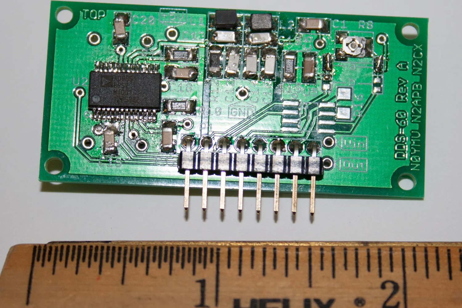
I have a nice DDS60. I have used this with my PIC-EL and an Arduino for previous work bench projects. (I also have some AD9850 andAD9851 adapter cards from eBay.)

DDS60

DDS60

I also have a nice si570 card from AA0ZZ / KangaUS which is pin compatible with the DDS60/DDS30. I use with the my Pic-EL from AA0ZZ.

AA0ZZ si570 card offered by KangaUS

AA0ZZ si570 card offered by KangaUS

I am looking to run some more si570 experiments but this time interfaced to the ATMEL AVR platform initially with an Arduino. I was doing searching for some code examples and run into a nice daughter board by WA6UFQ that I liked so much that I ordered one a couple of days ago.

WA6UVQ si570 controller card

WA6UVQ si570 controller card

While I wait for that card (kit) to arrive I started thinking that I would try to layout something similar in Eagle and mill a circuit board. This would give me a jump start on a future version if I want to extend the circuit to include a socket or ZIF for an AVR and some controls (switches or optical encoder.) 
si570 controller card example in Eagle

si570 controller card example in Eagle

One of the design/interface challenges that I am trying to noodle through is:

  1. Do I setup the daughter board with the minimum number of pins
    (minimum of 5 pins or 6 pins to use a standard sized part)
  2. Do I setup the board similar to the DDS30/DDS60 pin-out
  3. Do I setup the board similar to the WA6UFQ board that is coming in the mail

I really dislike having similar boards with dissimilar pin outs. At best it drives confusion and at worst it drives destruction when you mis-wire something and let the smoke out.

Initially I am leaning towards option #1 but I am still thinking about it. I have little bit of time since I have not converted the schematic to a board layout nor taken it to the CNC.

I don't have the proper voltage regulator on hand or I probably would have already milled out the board a few hours without as much thought about the what if portion of the design. (It is a prototype after all)

73 de NG0R

By: Comments Off

Monday nights are for quick projects

Tonight I had a meeting after dinner so I did not have much time for a project but I thought that my soldering iron was feeling lonely and neglected. I decided to put together an Arduino ISP shield from evilmadscientist.com that arrived in the mail a couple of days ago.

iPhone picture - Arduino ISP shield

iPhone picture - Arduino ISP shield

I had thought about making a board but this was too cheap to pass on. I might (or might not) have an AVR in-circuit-programmer sitting in my box of MCU parts (mainly PIC and ATMEL, and I have some Propeller parts too.) For $12 I figured that it was more important to have something on hand for when I need it vs. waiting for it when I need it. (It is just a matter of time.)

This board can be used to program Naked Arduino chips. (aka: AVR with the Arduino boot loader minus a circuit board or shield) or I can use it with the 6 pin or 10 pin break out as a standard AVR programmer.

It is a pretty simple project and should not take you more than 20-30 minutes to assemble and most of that is simply reading the instructions.

Here is a link to their wiki

Here is a link to how to use it.

Here is a nice article by Scott on how to use AVRDUDE to program AVR chips.

73 de NG0R

By: Comments Off

Parts in the mail - very cool

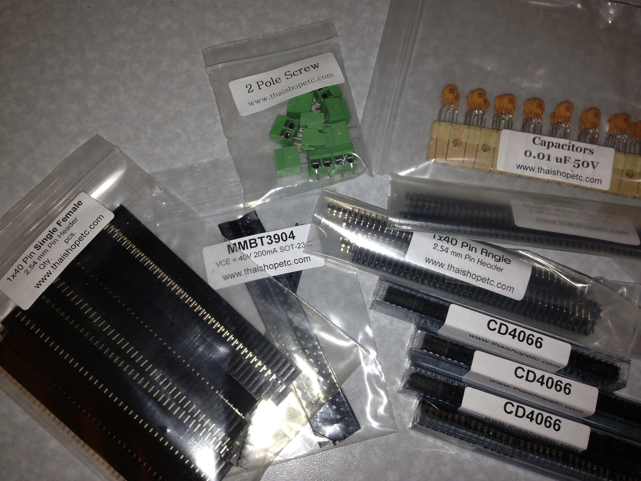
I love getting packages in the mail (and UPS, Fedex, etc) since a lot of them are parts for projects. Mouser, Digikey, ebay, etc.

iPhone photo of today's mail (aka parts run)

iPhone photo of today's mail (aka parts run)

While the parts are not very exciting it is important to continue to fill out the parts bins as time/money permits. When you decide to work on a project is handy to have the parts on hand vs. waiting 3-5 days for another parts shipment.

73 de NG0R