Laying out a PCB - Part 2
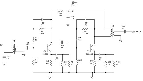
Here is the schematic from yesterday.

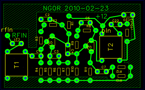
Here is an image of the updated single sided board layout.

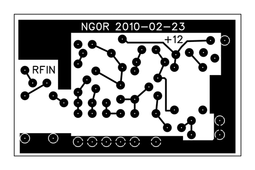
The image below is what it will look like when I print on the "print and peel" transfer
paper. The only difference is that it will mirrored at the final printing. (The tool
that I am using to read the Gerber file has a mirror option in the printer settings.)

The image below shows what the silk screen would look like if I was going to send
it off to a commercial board shop. In my case I will just use it as a layout tool
when I plug in the parts.

I hope to etch the board on Saturday pending other family related duties & projects.


Here is an image of the updated single sided board layout.
I changed the resistors and capacitors with some self brewed parts in FreePCB. The
new parts have 120 mil pads so that they can be drilled with a 1/16 drill. (I have
smaller bits on order.)
I created a new NPN TO-92 part with the emitter, base, and collector layer the same
as my PN2222 and 2N3904 layout. I created the parts with 120 mil pads.
I also created a part layout for some T50 toroids that will be used as the input and
output transformers.
The area with the cross hatch is the copper ground on the empty space on the board.

The image below is what it will look like when I print on the "print and peel" transfer
paper. The only difference is that it will mirrored at the final printing. (The tool
that I am using to read the Gerber file has a mirror option in the printer settings.)

The image below shows what the silk screen would look like if I was going to send
it off to a commercial board shop. In my case I will just use it as a layout tool
when I plug in the parts.

I hope to etch the board on Saturday pending other family related duties & projects.
