Dual Stage PN2222 Amp (Class A)
I have spent quite a bit of time this week exploring several different ideas:
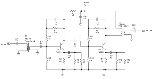
Here is the schematic that I put together. I moved one cap and replaced the 2N3094
NPNs with PN2222 (2N2222A) NPNs. I have a ton of PN2222 on hand so I would prefer
to use them up given how cheap they are. I guessed that input was some where around
25 ohms and the output was about 150-250 ohms. The input and output tranformers are
wound to keep the overall circuit compatible with approx 50 ohms. (The circuit
is similar to the single stage circuit that I had been testing with.)

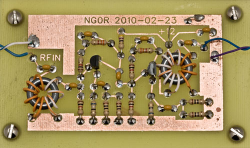
Here is the finished board. I etched the board Friday night after dinner and stuffed
the parts Sunday afternoon. The toriods are wound with left over CAT5 cable. The wire
is a nice size to work with on T50 cores.

Let's apply some power... nice... no smoke is released!
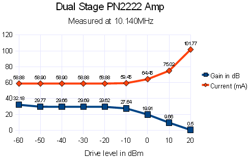
The graph below shows the that we are seeing almost 30dB of gain with drive levels
of -60dBm up to near -10dBm. The 2N3904 and PN2222 seem to lose gain near 0dBm of
drive input and this circuit follows that model. The current draw is about 58.8mA.
This amp is running in Class A mode.

This circuit should be fine at any of the HF frequencies. I happen to be testing with
10.140MHz because I have a larger project that I am working on at that frequency.
I have a oscillator and follower that is currently generating about -9dBm. Adding
this dual stage amp to the mentioned circuit would put this at approx +20dBm or 100mW
of RF. While that does not sound like huge power it is likely enough to feed a driver
or pre-driver stage for an amplifier.
Summary:
I meet all of the goals for this particular mini-project. I feel much more comfortable
putting together a design and making a home brew board that I am proud to show to
other people. A variation of this circuit will like make it into other projects in
the future.
73 de NG0R


Design a two stage amp (each stage with about 15db of gain)
Be stingy with the current budget
Convert the design into a home brew printed circuit board
Home brew the etchant
Here is the schematic that I put together. I moved one cap and replaced the 2N3094
NPNs with PN2222 (2N2222A) NPNs. I have a ton of PN2222 on hand so I would prefer
to use them up given how cheap they are. I guessed that input was some where around
25 ohms and the output was about 150-250 ohms. The input and output tranformers are
wound to keep the overall circuit compatible with approx 50 ohms. (The circuit
is similar to the single stage circuit that I had been testing with.)

Here is the finished board. I etched the board Friday night after dinner and stuffed
the parts Sunday afternoon. The toriods are wound with left over CAT5 cable. The wire
is a nice size to work with on T50 cores.

Let's apply some power... nice... no smoke is released!
The graph below shows the that we are seeing almost 30dB of gain with drive levels
of -60dBm up to near -10dBm. The 2N3904 and PN2222 seem to lose gain near 0dBm of
drive input and this circuit follows that model. The current draw is about 58.8mA.
This amp is running in Class A mode.

This circuit should be fine at any of the HF frequencies. I happen to be testing with
10.140MHz because I have a larger project that I am working on at that frequency.
The design is for wide band HF since there is no bandpass filter, lowpass filter,
or tank circuit.
The PN2222 and 2N3904 are interchangeable in this design. I would suspect that there
are quite a few other small signal NPN parts that you could drop in.
If you break this down and look at the first gain stage this design goes beyond a
simple DC bias. C2 and R3 provide AC feedback in addition to the emitter with C3,
R6, and R7. Those two AC sections increase the gain and decrease the current
consumed. Adding those components decreases the current consumption by about 20mA
to get the same level of gain.
I have a oscillator and follower that is currently generating about -9dBm. Adding
this dual stage amp to the mentioned circuit would put this at approx +20dBm or 100mW
of RF. While that does not sound like huge power it is likely enough to feed a driver
or pre-driver stage for an amplifier.
Summary:
I meet all of the goals for this particular mini-project. I feel much more comfortable
putting together a design and making a home brew board that I am proud to show to
other people. A variation of this circuit will like make it into other projects in
the future.
73 de NG0R
