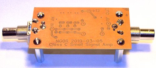
Triple PN2222 Class C Amp
Tonight I got back to the work bench to work on one of my projects.

The image below is an old schematic and the three 50 ohm resistors were replaced with a single resistor so that the circuit presents a 50 ohm impedance to the signal generator.

I had to hunt for the schematic and the image below so that I could remember what I was thinking when I came up with this experiment.

This is a Class C amp using three parallel PN2222 transistors. The idea was based upon some schematics that I saw doing something similar with FETs. If it can be done with a FET it should be possible using something like a PN2222.
I printed up the board about a month ago but had not gotten around to finishing the project. So tonight while participating in the "Builders Net" on EchoLink (using my Netbook+Qtel at the work bench) I drilled the board using my dremel-press. I recently bought a bunch of BNC right angle PCB connectors. My original design assumed that I would connect the board to the BNC via a short lead or some mini coax. I decided to mod the PCB tonight to accept the new connectors right on the board.
When time permits one evening this week I would like to stuff the parts. Once that is completed I can connect the signal generator and power meter. There are three things that I would like to measure:


The image below is an old schematic and the three 50 ohm resistors were replaced with a single resistor so that the circuit presents a 50 ohm impedance to the signal generator.

I had to hunt for the schematic and the image below so that I could remember what I was thinking when I came up with this experiment.

This is a Class C amp using three parallel PN2222 transistors. The idea was based upon some schematics that I saw doing something similar with FETs. If it can be done with a FET it should be possible using something like a PN2222.
I printed up the board about a month ago but had not gotten around to finishing the project. So tonight while participating in the "Builders Net" on EchoLink (using my Netbook+Qtel at the work bench) I drilled the board using my dremel-press. I recently bought a bunch of BNC right angle PCB connectors. My original design assumed that I would connect the board to the BNC via a short lead or some mini coax. I decided to mod the PCB tonight to accept the new connectors right on the board.
When time permits one evening this week I would like to stuff the parts. Once that is completed I can connect the signal generator and power meter. There are three things that I would like to measure:
- Power consumption
- Input drive level limits/requirements
- Output power level
