Playing with PCBs and 2N7000 amps
I am planning on making some printed circuit boards this weekend. Since I need to get out the chemicals & related supplies I might as well make several boards. So in addition to the board for the parallel NPN transistors I thought that I would make up some 2N7000 FET experiments as well.
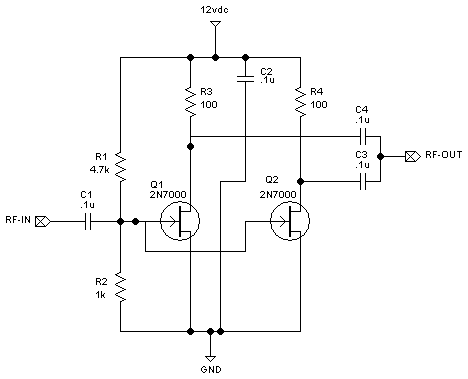
The circuit below is a dual FET design. The FETs are in parallel running in class
A. The Gate is biased for approximately 2 volts of DC drive with virtually no current
with assuming a bench power supply of 12-13.5 volts. (R3 and R4 are high values
for current limiting aka to avoid self destruction.) The 2N7000 is rated for 200mA
of safe current. (200mA would suggest a drain resistor of approximately 68ohms.) I
don't really want to waste that much current but I want to see what this will draw.
I would prefer that it consume current less than my NPN experiments which is about
25mA per device with 15 to 17dB of gain per device. (I assume that I will be changing
the drain resistors once I know more about this FET.)

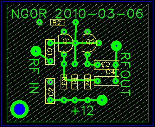
The image below shows what it looks like after spending a little bit of time bonding
with FreePCB. (The blue circle in the bottom left is a small hole to hold/retrieve
the board in the etchant bath.)

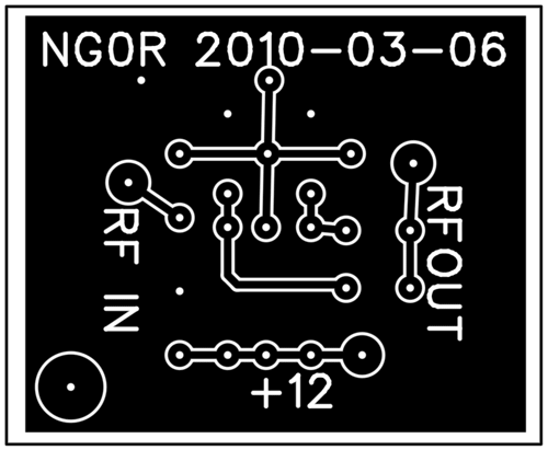
The image below shows what the copper will look like (in black.) The white
areas will be removed by the etchant. The board looks big on the web but it is actually
only about 1.5 x 1.5 inches total. (If I removed the text and extra space it could
easily be condensed down to less than 1 x 1 inch.)

I don't know that I would would ever really use a design like this in the real world
but I want to get a feel for how it performs. I have NOT used FETs in any of my designs
or experiments yet so this is a good starting point.
Bipolar Junction Transistors are current devices. Field Effect Transistors are voltage
devices. It is interesting working with each of them as they have different design
considerations.
Some additional notes (before people start sending me emails):
73 de NG0R


The circuit below is a dual FET design. The FETs are in parallel running in class
A. The Gate is biased for approximately 2 volts of DC drive with virtually no current
with assuming a bench power supply of 12-13.5 volts. (R3 and R4 are high values
for current limiting aka to avoid self destruction.) The 2N7000 is rated for 200mA
of safe current. (200mA would suggest a drain resistor of approximately 68ohms.) I
don't really want to waste that much current but I want to see what this will draw.
I would prefer that it consume current less than my NPN experiments which is about
25mA per device with 15 to 17dB of gain per device. (I assume that I will be changing
the drain resistors once I know more about this FET.)

The image below shows what it looks like after spending a little bit of time bonding
with FreePCB. (The blue circle in the bottom left is a small hole to hold/retrieve
the board in the etchant bath.)

The image below shows what the copper will look like (in black.) The white
areas will be removed by the etchant. The board looks big on the web but it is actually
only about 1.5 x 1.5 inches total. (If I removed the text and extra space it could
easily be condensed down to less than 1 x 1 inch.)

I don't know that I would would ever really use a design like this in the real world
but I want to get a feel for how it performs. I have NOT used FETs in any of my designs
or experiments yet so this is a good starting point.
Bipolar Junction Transistors are current devices. Field Effect Transistors are voltage
devices. It is interesting working with each of them as they have different design
considerations.
Some additional notes (before people start sending me emails):
The input impedance of this circuit is pretty high. It is not clear what high impedance
is other than to say it could be way north of 1K. In this initial test I am not making
any attempt to match the input. (That is why it is test.)
If I was going to try to match the input to something like my signal generator I would
probably use a 1:4 or 1:5 turns ratio to take the 50 ohm source and transform it to
between 800 and 1250 ohms.
The output of this should be approximately what the drain resistor value is. In this
case it should see two 100 ohm resistors in parallel or 50 ohms. (I might be changing
these resistors once I do some testing so it is a bit early to be too worried about
matching the circuit. I would also need to now what the next circuit stage is that
we need to integrate with.) It would be easy enough to wind a transformer on a
T50-43 core to step-up/step-down as needed.
FETs are voltage sensitive. Looking at the data sheet it appears that 60 volts
is the max that the 2N7000 can handle. In a design for a "real" circuit it might be
worth considering adding a zener diode to the drain to shunt off the excess voltage
should it appear. (An example is running this circuit without having a load attached...
it could spike the voltage on the drain to a fatal level. I have a limited number
of 33 volt zeners on hand but that would potential for a design like this. For this
test I am not going to worry about it. If I decide to use FETs in a "real" project
I would probably include them.)
73 de NG0R
