QRSS Oscillator for 30m
Tonight was a lot of fun. I finally got back to the work bench to run a couple of tests. I have a bunch of crystals for 10.140MHz but they seem really be 10.138MHz. This is NOT in the QRSS sub band and I figured that I could probably "pull" the crystal up to 10.140.100 sub band. --The real question is what size capacitor would it take.

I drew up a quick schematic (on paper) that looks something like the image above. I then pulled out a couple of variable capacitors. Initially I tried a 12-250pF and then moved to a 4pF-40pF. The magic seems to be about 15-18pF to it to the proper sub band for QRSS operation.

I was surprised at how stable it was. I had it running on workbench for about an hour and it only moved about 1 hertz across 10 minutes and no more than 2-3 hertz in an hour. That is pretty darn stable for a breadboard.

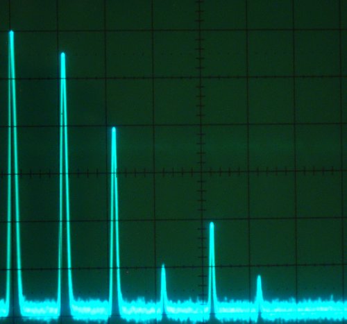
The image below shows the fundamental signal and the first five harmonics. It is pretty rich so I could easily pick out and tune any (or many others) with a tank circuit if needed.

10MHz x 10dB divisions
This is more than stable enough for QRSS operation. You would need to add a couple of simple gain stages with some small signal parts like a PN2222 or 2N3904 running in class A + a simple transistor final + a low pass filter. (All of these other stages are listed on this blog if you search around a bit through previous posts.)
Some notes about the variable capacitors:
12-250pF will cover 10,138,466 to 10,140,620 hertz
4-40pF will cover 10,139,228 to 10,142,495 hertz
I found that 15-18pf was needed to get into the QRSS sub band with my components.
Next Steps:


I drew up a quick schematic (on paper) that looks something like the image above. I then pulled out a couple of variable capacitors. Initially I tried a 12-250pF and then moved to a 4pF-40pF. The magic seems to be about 15-18pF to it to the proper sub band for QRSS operation.

I was surprised at how stable it was. I had it running on workbench for about an hour and it only moved about 1 hertz across 10 minutes and no more than 2-3 hertz in an hour. That is pretty darn stable for a breadboard.

The image below shows the fundamental signal and the first five harmonics. It is pretty rich so I could easily pick out and tune any (or many others) with a tank circuit if needed.

10MHz x 10dB divisions
This is more than stable enough for QRSS operation. You would need to add a couple of simple gain stages with some small signal parts like a PN2222 or 2N3904 running in class A + a simple transistor final + a low pass filter. (All of these other stages are listed on this blog if you search around a bit through previous posts.)
Some notes about the variable capacitors:
12-250pF will cover 10,138,466 to 10,140,620 hertz
4-40pF will cover 10,139,228 to 10,142,495 hertz
I found that 15-18pf was needed to get into the QRSS sub band with my components.
Next Steps:
- I need to test a couple of different ideas for what I am going to use for my "finals"
- Test how I want to "key" the whole transmit stage
- Layout a circuit board for a prototype
