QRSS Prototype
I finally got around to applying power to the prototype this afternoon.
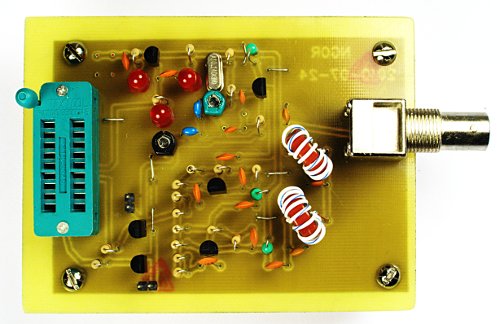
I did not spend a lot of time but here is what I recorded in about 20 minutes of bench time:
I did not test it with a PIC, but I instead used the header pins.
Specs:
Good:
Bad or unclear:
I will need to spend some more time with it when time permits... need to run off to dinner with my family.
73 de NG0R

I did not spend a lot of time but here is what I recorded in about 20 minutes of bench time:
I did not test it with a PIC, but I instead used the header pins.
Specs:
- 12vdc @.34amp
- 26dBm or about 400mW of RF @ 10,140,030MHz
- All harmonics are at least 47db down
Good:
- It made a LOT of RF
- It was extremely clean
- It starts up reliably
Bad or unclear:
- It does not appear that my frequency shift with the second variable capacitor is working
I will need to spend some more time with it when time permits... need to run off to dinner with my family.
73 de NG0R