More... Reverse Biased Diodes
I am still looking for some other options for a better method of handling my tuning for my next QRSS prototype. I decided to revisit the bread board and take some additional measurements.

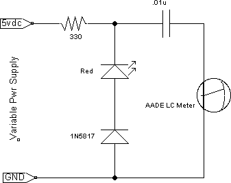
I was wondering if a series red LED + 1N5817 (both are reversed biased) might give me the range that I need within a 0 to 5vdc window. (I will be using a PIC 16F628A for pulse width modulation so 5vdc is my upper range.)

The results are promising based upon the graph below. My design goal is about 12-20pF. I think that I need about 18pF based upon some earlier prototypes.

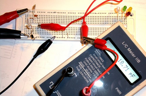
This picture shows you what a pain it is try to measure these parts and then swap out new combinations. At some point I will design a little prototyping adapter for my LC meter so that I can do this right on the front of the meter without any jumpers.

I tried one other combination that provided a very granular range.
Reverse biased in series 1N5817 + Red Led + 1N5817
0-5vdc = 6-18pF
I have four different variations that I have tested over the past couple of days that will get me into the ball park to differing degrees. (granular tuning vs. tuning range vs. parts count)
Options 3 & 4 provides more granular tuning
I will need to ponder this a bit to determine which path I like the best.
73 de NG0R


I was wondering if a series red LED + 1N5817 (both are reversed biased) might give me the range that I need within a 0 to 5vdc window. (I will be using a PIC 16F628A for pulse width modulation so 5vdc is my upper range.)

The results are promising based upon the graph below. My design goal is about 12-20pF. I think that I need about 18pF based upon some earlier prototypes.

This picture shows you what a pain it is try to measure these parts and then swap out new combinations. At some point I will design a little prototyping adapter for my LC meter so that I can do this right on the front of the meter without any jumpers.

I tried one other combination that provided a very granular range.
Reverse biased in series 1N5817 + Red Led + 1N5817
0-5vdc = 6-18pF
I have four different variations that I have tested over the past couple of days that will get me into the ball park to differing degrees. (granular tuning vs. tuning range vs. parts count)
- Reverse Biased 1N5817... a bit too much capacitance by it's self
- Parallel 10-30pF variable cap + rev biased Red LED
- Series rev biased 1N5817 + rev biased Red LED
- Series rev biased 1N5817 + rev biased Red LED + rev bias 1N5817
Options 3 & 4 provides more granular tuning
I will need to ponder this a bit to determine which path I like the best.
73 de NG0R
